


Servo System
Your Professional Servo System Supplier
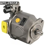
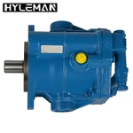
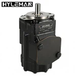
Ningbo Hyleman Hydraulics Co., Ltd is a scientific and innovative company integrating R & D, production, sales and service of high-quality hydraulic pumps, motors, gear reducers and other hydraulic products.Hyleman mainly supply A10V, A4V, A4VG, A11V, A15V, A20V,A2FO,A2FM, A6VM, PV, PVP, PVAC, PVB, PVQ, PVH series piston pumps and motors ; T6,T7,V,VQ, M5A, M5B, M4C, M4D, M4E, 25M, 35M, 45M, 50M series vane pumps and motors;C101/102, G101/102, PGP/PGM, 30/31,50/51, 75/76 series gear pumps and motors.
Why choose us
QUALITY ASSURANCE
Through the honing and innovation of Hyleman people, Hyleman series products can not only perfectly replace the original products, but also realize the seamless exchange and connection of all the parts.
GOOD SERVICE
Hyleman are devoting to provide our clients with the best quality products, and the comprehensive solutions of hydraulics.
PRODUCT APPLICATION
Hyleman series products are widely used in engineering machinery, plastic machinery, metallurgical machinery, environmental sanitation machinery, mining machinery, marine machinery, packaging machinery, port machinery and various hydraulic equipment, which are highly praised by clients.
PRODUCT EXPORT
Through the honing and innovation of Hyleman people, Hyleman series products can not only perfectly replace the original products, but also realize the seamless exchange and connection of all the parts. Hyleman products have been exported to more than 70 countries and regions around the world.


Servo System Introduction
Servo system is a product developed on the basis of frequency conversion technology. It is an automatic control system that takes a mechanical position or angle as the control object. In addition to speed and torque control, the servo system can also perform precise, fast, and stable position control.


Main functions of Servo System
1.Control of high power load with small power command signal.
2.In the absence of mechanical connection, the input shaft controls the output shaft at the far distance to realize the long distance synchronous drive.
3.Make the output mechanical displacement accurately track electrical signals, such as recording and indicating instruments.
Key Features of Servo Systems
Closed-loop Control:
The feedback allows for adjustments based on the difference between the desired and actual positions (or speeds), leading to higher accuracy.
High Precision:
Servo systems can achieve very precise control, which is essential in applications like robotics, CNC machinery, and automated systems.
Dynamic Response:
They can respond quickly to changes in input or disturbances, making them suitable for applications requiring rapid adjustments.
Types of Controllers in Servo Systems
PID Controllers (Proportional-Integral-Derivative)
These are the most common types of controllers in servo systems. They continuously adjust the motor’s output by considering the difference between the desired and actual values, calculating the proportional, integral, and derivative errors. This allows for smooth and accurate control.
Position Controllers
These are used when the system requires precise positioning. For example, in CNC machinery or 3D printing, where the exact location of a tool or nozzle is critical, position controllers come into play.

Velocity Controllers
When speed is the main factor, velocity controllers regulate the motor’s speed rather than its position. This is common in applications like conveyor belts or electric vehicles.
Torque Controllers
These controllers focus on controlling the motor’s torque, making them ideal for applications that require consistent force, such as robotic grippers or presses.
The structure of the servo system
Comparison link
The comparison link is the link that compares the input command signal with the feedback signal of the system to obtain the deviation signal between the output and the input and is usually implemented by a special circuit or computer.
Controller
The controller is usually a computer or PID (proportional, integral, and derivative) control circuit. Its main task is to transform the deviation signal output by the comparison element to control the actuator to act as required.
Implementation link
The function of the execution link is to convert various forms of input energy into mechanical energy according to the requirements of the control signal to drive the controlled object to work. The executive components in the mechatronics system generally refer to various motors or hydraulic and pneumatic servo mechanisms.
Controlled object
The controlled object is a mechanical arm or a mechanical working platform.
Testing link
The detection link refers to a device that can measure the output and convert it into the dimension required by the comparison link, which generally includes a sensor and a conversion circuit.

Servo System Configuration Example

Features
Precise, High-speed Control
Servomotors excel at position and speed control.
Precise and flexible positioning is possible.
Servomotors do not stall even at high speeds. Deviations due to large external forces are corrected because encoders are used to monitor movement.
Fully-closed Loop
The most reliable form of closed loop. A fully-closed loop is used when high precision is required.
The motor is controlled while directly reading the position of the machine (workpiece or table) using a linear encoder and comparing the read position with the command value (target value). Therefore, there is no need to compensate for gear backlash between the motor and mechanical system, feed screw pitch error, or error due to feed screw torsion or expansion.
Fully-closed Loop System Configuration Example

Semi-closed Loop
This method is commonly used in servo systems.
It is faster and has better positioning precision than an open loop.
Typically an encoder or other detector is attached behind the motor. The encoder detects the rotation angle of a feed screw (ball screw) and provides it as feedback of the machine (workpiece or table) travel position. This means that the position of the machine is not detected directly. The characteristics depend on where the detector is installed.
|
Installation location of |
Behind motor |
Motor side of |
Opposite of |
|
Gear backlash |
Compensation |
Compensation |
← |
|
Ball screw or nut torsion |
Affected |
← |
Hardly affected |
|
Ball screw expansion or |
Affected |
← |
← |
|
Ball screw pitch error |
Compensation |
← |
← |
Semi-closed Loop System Configuration Example

A stepper motor is used instead of a servomotor. There is no feedback loop.
The overall configuration is simple. Positioning can be performed at low cost, but gear and ball screw backlash and pitch errors cannot be compensated. When a stepper motor stalls, an error will occur between the command value and the actual movement. This error cannot be compensated.
Open loop control is suitable for low-precision, low-cost, lowspeed, and low-load-change applications.

Open Loop System Configuration Example

our factory


