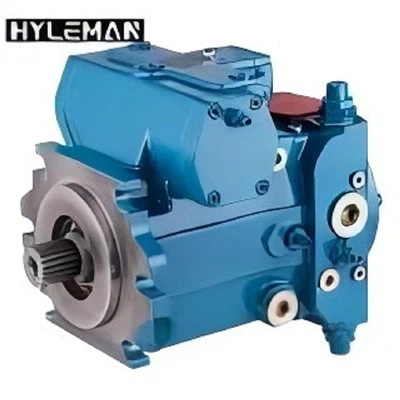
As a trusted supplier of external gear pumps, I understand the critical role these pumps play in various industrial applications. Designing an effective control system for an external gear pump is essential to ensure optimal performance, reliability, and efficiency. In this blog post, I will share my insights and experiences on how to design such a control system, drawing on my expertise as a supplier in this field.
Understanding the Basics of External Gear Pumps
Before delving into the design of a control system, it's important to have a solid understanding of external gear pumps. These pumps operate on the principle of positive displacement, using two meshing gears to transfer fluids. As the gears rotate, they create a volume change that draws fluid into the pump and then discharges it at a higher pressure.
External gear pumps are known for their simplicity, durability, and ability to handle a wide range of fluids, including oils, fuels, and other viscous liquids. They are commonly used in applications such as hydraulic systems, lubrication systems, and automotive transmissions.
Key Considerations in Control System Design
When designing a control system for an external gear pump, several key factors need to be considered:
1. Flow and Pressure Requirements
The first step is to determine the required flow rate and pressure for the specific application. This information will help in selecting the appropriate pump size and determining the control system's output requirements. For example, in a hydraulic system, the flow rate and pressure are crucial for driving actuators and performing specific tasks.
2. Pump Efficiency
Efficiency is a critical factor in pump operation. A well-designed control system should optimize the pump's efficiency by adjusting the pump speed or other operating parameters based on the demand. This not only reduces energy consumption but also extends the pump's lifespan.
3. System Stability
Maintaining system stability is essential to prevent fluctuations in flow and pressure. The control system should be able to compensate for changes in load, temperature, and other factors that can affect the pump's performance. This can be achieved through the use of feedback control loops and appropriate sensors.
4. Safety and Reliability
Safety is always a top priority in industrial applications. The control system should incorporate safety features such as overpressure protection, temperature monitoring, and emergency stop functions. Additionally, it should be designed for high reliability to minimize downtime and maintenance costs.
5. Compatibility with Other Components
The control system should be compatible with other components in the system, such as valves, motors, and sensors. This ensures seamless integration and optimal performance of the entire system.


Designing the Control System
1. Selecting the Right Sensors
Sensors play a crucial role in a control system by providing real-time information about the pump's operating conditions. Some common sensors used in external gear pump control systems include:
- Flow sensors: These sensors measure the flow rate of the fluid being pumped. They can be used to monitor the pump's output and ensure that it meets the required specifications.
- Pressure sensors: Pressure sensors measure the pressure of the fluid at various points in the system. They are used to detect overpressure conditions and adjust the pump's operation accordingly.
- Temperature sensors: Temperature sensors monitor the temperature of the fluid and the pump itself. High temperatures can indicate a problem with the pump or the system and may require corrective action.
2. Choosing the Control Algorithm
The control algorithm is the heart of the control system. It determines how the system responds to changes in the input signals and adjusts the pump's operation to achieve the desired output. There are several control algorithms available, including:
- Proportional-Integral-Derivative (PID) control: This is a widely used control algorithm that uses proportional, integral, and derivative terms to adjust the output based on the error between the desired and actual values.
- Fuzzy logic control: Fuzzy logic control is a more advanced control algorithm that uses fuzzy sets and rules to handle uncertain and imprecise information. It can be particularly useful in applications where the system behavior is complex and difficult to model.
- Model-based control: Model-based control uses a mathematical model of the system to predict its behavior and adjust the control inputs accordingly. This approach can provide more accurate and efficient control, but it requires a detailed understanding of the system dynamics.
3. Implementing the Control System
Once the sensors and control algorithm have been selected, the next step is to implement the control system. This typically involves the following steps:
- Hardware selection: Select the appropriate hardware components, such as a microcontroller, motor driver, and power supply, to implement the control system.
- Software development: Develop the software code to implement the control algorithm and interface with the sensors and actuators.
- Testing and calibration: Test the control system in a laboratory environment to ensure that it operates as expected. Calibrate the sensors and adjust the control parameters to optimize the system performance.
- Installation and commissioning: Install the control system in the actual application and commission it to ensure that it works correctly in the field.
Examples of Control System Applications
To illustrate the practical application of the control system design principles discussed above, let's consider a few examples:
1. Hydraulic System for an Excavator
In an excavator hydraulic system, an external gear pump is used to supply hydraulic fluid to the various actuators, such as the boom, arm, and bucket cylinders. The control system for this application needs to be able to adjust the pump's flow rate and pressure based on the operator's commands and the load requirements.
A typical control system for an excavator hydraulic system may include flow sensors, pressure sensors, and a microcontroller. The microcontroller uses a PID control algorithm to adjust the pump speed based on the desired flow rate and pressure. The flow sensors measure the actual flow rate, and the pressure sensors measure the pressure at various points in the system. The feedback signals from the sensors are used to adjust the control output and maintain the desired operating conditions.
For more information on external gear pumps for excavator machinery, you can visit Hot Sale Parker External Gear Pump For Excavator Machinery CASE580SK-D140801-MG229D149283121124A1.
2. Lubrication System for a Large Industrial Machine
In a large industrial machine, such as a compressor or a generator, an external gear pump is used to supply lubricating oil to the various moving parts. The control system for this application needs to ensure a constant flow of oil at the correct pressure to prevent wear and tear on the machine components.
A control system for a lubrication system may include a flow sensor, a pressure sensor, and a solenoid valve. The microcontroller uses a simple on-off control algorithm to open and close the solenoid valve based on the pressure readings from the sensor. If the pressure drops below a certain threshold, the solenoid valve is opened to allow more oil to flow into the system. If the pressure rises above the threshold, the solenoid valve is closed to reduce the flow.
3. Fuel Delivery System for a Diesel Engine
In a diesel engine, an external gear pump is used to supply fuel from the fuel tank to the injectors. The control system for this application needs to ensure a precise and consistent flow of fuel to the engine to maintain its performance and efficiency.
A control system for a fuel delivery system may include a flow sensor, a pressure sensor, and a fuel injection pump controller. The microcontroller uses a model-based control algorithm to adjust the fuel injection pump's operation based on the engine's speed, load, and other parameters. The flow sensor measures the actual fuel flow rate, and the pressure sensor measures the fuel pressure at the injectors. The feedback signals from the sensors are used to adjust the control output and ensure that the engine receives the correct amount of fuel.
For more information on hydraulic pumps, you can visit Casappa Hydraulic Pump Price PGP20 PGP25 and Parker Meteris Casappa PGP20 PGP25 Commercial Intertech Hydraulic Pump.
Conclusion
Designing an effective control system for an external gear pump is a complex but rewarding task. By considering the key factors discussed in this blog post and following the design principles outlined here, you can ensure that your control system meets the specific requirements of your application and provides optimal performance, reliability, and efficiency.
If you are interested in learning more about external gear pumps or need assistance with designing a control system for your application, please feel free to contact us. We have a team of experienced engineers who can provide you with customized solutions and support.
References
- [1] Hydraulic Pump Handbook, Fourth Edition, Edited by Heinz P. Bloch and Andrew L. Budris.
- [2] Control Systems Engineering, Fourth Edition, by Norman S. Nise.
- [3] Instrumentation and Control Systems, Third Edition, by Alan S. Morris.